
GENERAL AIRSTAGE | TECHNICAL REFERENCE
Air Conditioning Controls - Selection & Features
Infrared Remotes, Wired Controllers, KAGAMI, VRF Central Controls and Transmission Wiring
GENERAL AIRSTAGE offers a range of local and central controllers to suit residential, commercial and VRF installations. This guide explains the features, applications and key differences between controller options to assist with product selection and technical support.
1. Controller Selection | 2. Infrared Controllers | 3. Simple Wired Controllers | 4. Touch Panel Controllers | 5. KAGAMI | 6. Local Control Arrangements | 7. VRF Central Controls | 8. VRF Wiring | 9. Selection Checklist
1. Controller Selection Guide
Select a controller based on the system type, required functionality, number of connected indoor units and user requirements.
| Controller | Application | Key Features |
|---|---|---|
| Comfort Infrared | Compatible split systems | Basic comfort, fan, temperature and timer controls |
| Lifestyle Infrared | Compatible split systems | Weekly timer, energy functions and additional operating options |
| UTY-RSRYT1 / UTY-RHRYT1 | Simple wired control | Cost-effective temperature and fan adjustment |
| UTY-RNRT | Ducted single and multi split | Touch panel, scheduling and eight-zone compatibility |
| UTY-RNRYT6 | Single and multi split | Touch panel, scheduling, temperature sensor and vane settings |
| UTY-RVRY KAGAMI | Residential and commercial applications | Customisable display, occupancy sensor and Bluetooth setup |
| UTY-DCGYZ4 | VRF central control | Up to 100 indoor and 100 outdoor units |
| UTY-DTGYZ1 | Larger VRF installations | Up to 400 indoor and 100 outdoor units |
| Software-Based VRF Control | Large and multi-site installations | PC-based monitoring, energy management and scheduling |
2. Infrared Controllers - Comfort vs Lifestyle
Infrared controllers provide wireless local control of compatible indoor units. The supplied controller is included with the indoor unit and is treated as a spare part for replacement purposes.
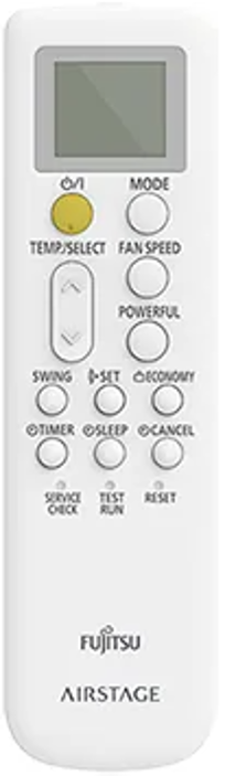
Comfort Infrared Controller
The Comfort controller provides straightforward operation for everyday air conditioning requirements.
- Display of operating mode, set temperature, vane position and fan speed.
- Temperature adjustment in 0.5°C increments.
- Five fan settings: Auto, Quiet, Low, Medium and High.
- Powerful mode for maximum airflow until the set temperature is achieved or for up to 20 minutes.
- Vertical and horizontal swing functions where supported.
- On/Off timers in 30-minute increments.
- Sleep timer with temperature adjustments for up to four hours in heating or two hours in cooling.
- Economy operation and Demand Response Enabled Device (DRED) capability where applicable.
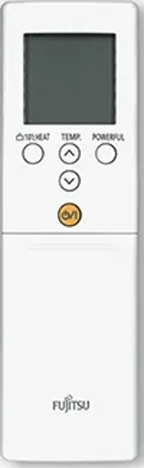
Lifestyle Infrared Controller
The Lifestyle controller includes the core Comfort functions together with additional scheduling and energy-management features.
- Clock and weekly timer with up to four settings per day.
- 10°C Heat operation.
- Human sensor for motion-based control.
- Low-noise operation using compressor speed reduction.
- Economy and energy-saving functions.
- Powerful, Sleep, Swing, Timer and fan-speed functions.
- DRED capability where applicable.
3. Simple Wired Controllers
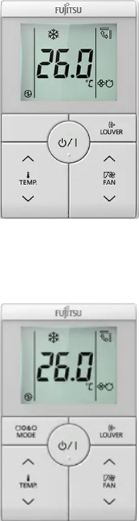
UTY-RSRYT1 and UTY-RHRYT1
These controllers provide straightforward, cost-effective wired room control with a simplified user interface.
- Temperature setpoint display and adjustment.
- Temperature adjustment in 0.5°C increments.
- Four fan settings: Auto, Quiet, Low and High.
- Operating mode indication using symbols and text.
- Up/down vane operation where compatible.
- Mode button functionality available as an option on UTY-RSRYT1 only.
4. Touch Panel Wired Controllers
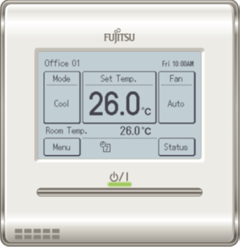
UTY-RNRT - Ducted Split Controller
The UTY-RNRT is identified in the presentation as the wired controller supplied with compatible ducted single and multi split indoor units. This does not include VRF.
- Touch panel with silver On/Off button.
- Built-in room temperature sensor.
- Automatic heating/cooling changeover with a stated ±2°C operating variation.
- Five heating fan speeds and six cooling settings, with the sixth cooling setting identified as fan only.
- Compatibility with up to eight On/Off zones.
- On/Off timer in 30-minute intervals.
- Sleep timer.
- Weekly timer with up to four settings per day.
- Setback timer with two scheduled setbacks per day.
- Defrost indication.
- Automatic restart.
- 10°C Heat operation.
- Economy operation and DRED capability.
- Optional remote temperature sensor.
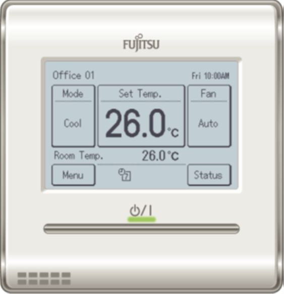
UTY-RNRYT6 - Single and Multi Split Controller
This touch panel controller provides advanced local operation for compatible single and multi split systems.
- Touch panel and silver On/Off button.
- Built-in temperature sensor.
- Automatic heating/cooling changeover.
- Five heating fan speeds and six cooling settings as described in the presentation.
- Vane directional control for compatible non-ducted indoor units.
- 30-minute On/Off timer increments.
- Weekly timer with up to four settings per day.
- Sleep timer and two daily setback periods.
- Defrost indication and Auto Restart.
- 10°C Heat and Economy functions.
- DRED capability.
- Optional remote temperature sensor.
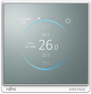
5. KAGAMI Wired Controller - UTY-RVRY
The KAGAMI controller provides a customisable user interface for compatible single and multi split applications.
Typical applications: Car dealerships, showrooms, hospitality venues, penthouses, residential properties and schools.
User Interface and Customisation
- Touch-panel display with optional user-selected logo.
- Configurable on-screen operating options.
- Ability to restrict On/Off control, mode selection and fan control.
- Selectable upper and lower temperature limits for each mode.
- Administrator, installer and child-lock password functions.
- Multilingual interface and daylight-saving option.
Operating Features
- Built-in room temperature sensor.
- Occupancy sensor with selectable shut-off periods of 45, 60, 90, 120 or 180 minutes.
- Automatic mode changeover with ±2°C operating variation.
- Vane directional control for compatible indoor units.
- Sleep timer, setback timer and weekly scheduling.
- Two weekly timer programs and a Day Off function.
- Defrost indication, Auto Restart and 10°C Heat operation.
- Economy function and DRED capability.
AIRSTAGE REMO Set App
The KAGAMI controller supports Bluetooth configuration using the AIRSTAGE REMO Set application.
Installers can configure controller settings, save configurations and deploy the same settings to additional compatible controllers. This can reduce repetitive on-site programming and support consistent commissioning across multiple rooms.
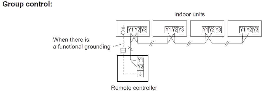
6. Local Controller Installation Arrangements
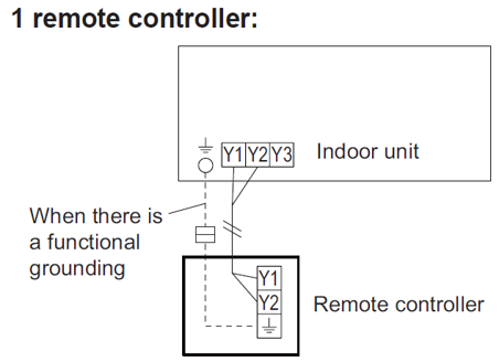
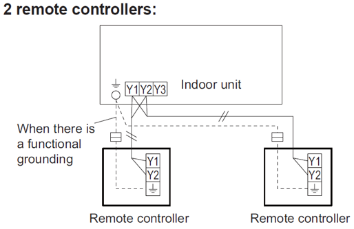
The presentation identifies the following local controller configurations:
| Arrangement | Description |
|---|---|
| One controller, one indoor unit | Individual control of one indoor unit. |
| One controller, multiple indoor units | Identical control of up to 16 connected indoor units, subject to compatibility. |
| Two controllers, one indoor unit | Dual control arrangement where supported. |
Controller grouping, master/sub-controller configuration, wiring and address settings must be checked against the applicable installation manual.
7. VRF Central Control Systems
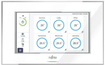
Central controllers allow multiple indoor units to be monitored and controlled through a common interface, with additional scheduling, user restrictions and operational monitoring functions.
UTY-DCGYZ4 - VRF Central Controller
| Feature | Specification |
|---|---|
| Indoor Units | Up to 100 |
| Outdoor Units | Up to 100 |
| Interface | Touch screen |
| Scheduling | 365-day scheduling |
| Remote Operation | Browser-based access |
Additional functions:
- Group display options for 2, 6 or 12 groups.
- Multilingual display and colour-coded operational status.
- Temperature range limits.
- Remote controller prohibition settings.
- Password protection and email notifications.
- Low-noise scheduling.
- External input, error output and operational status output connections.
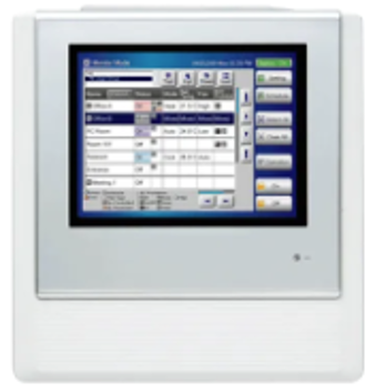
UTY-DTGYZ1 - VRF Touch Panel Controller
| Feature | Specification |
|---|---|
| Display | 7.5-inch touch screen |
| Indoor Units | Up to 400 |
| Outdoor Units | Up to 100 |
| Groups | Up to 64 per controller |
| Scheduling | 365-day timer and up to 30 weekly schedules |
Additional functions:
- Icon or list monitoring views.
- Browser access and remote monitoring.
- Monitoring, Control and Installer access levels.
- Up to five On/Off operations in weekly scheduling.
- Temperature limits and local controller restrictions.
- Password protection and email notifications.
- Low-noise scheduling.
- External inputs and operational/error outputs.
- Optional power apportioning functionality.
Software-Based VRF Central Control
The presentation describes software-based VRF controllers for larger installations requiring monitoring, scheduling, reporting and energy management through a field-supplied computer.
- Connection through an Echelon USB adapter to the VRF X1/X2 transmission network.
- Up to 1,600 indoor units as stated in the presentation.
- Connection arrangements involving up to 10 computers.
- Remote management of up to five additional sites using optional UTY-PLGXR2.
- Compatible power apportioning and energy-saving management functions.
- 3D building, floor, list and tree monitoring displays.
- Error notifications, email alerts, error history and operational history.
- Operating patterns, temperature limits and web operation.
- 365-day scheduling and low-noise scheduling.
- Up to 100 network converters, with individual control or groups of up to 16 indoor units.
The source presentation lists different model codes for the software-based VRF controls: UTY-ALGYZ1 / UTY-APGYZ1 and UTY-ALGXZX1 / UTY-APGXZ1. Confirm the correct current model numbers, software licences and accessories before quotation or ordering. The source also contains an additional 400-unit capacity figure that is not clearly defined.
8. VRF Transmission Wiring and Network Design
The presentation identifies two transmission wiring arrangements: serial and parallel. The overall maximum transmission length stated is 3,600 metres, subject to the applicable system requirements.
Serial Wiring
Master outdoor units, indoor units and central controllers are connected along a continuous transmission circuit.
Advantage: Can reduce the quantity of cabling required through building risers.
Parallel Wiring
Each outdoor unit connects to its associated indoor units, with outdoor systems subsequently connected together through the transmission network.
Advantages:
- Individual systems can be isolated for troubleshooting.
- Networks can be divided into smaller sections for staged commissioning.
- Cable faults may be easier to isolate.
- Automatic addressing is possible; however, the presentation advises this is not preferred for installations involving a BMS.
Network Length and Signal Amplifiers
| Requirement | Presentation Guidance |
|---|---|
| Maximum Total Transmission Length | 3,600 metres |
| Signal Amplifiers - Distance | Required for every 500 metres of transmission wiring, subject to the applicable system manual. |
| Signal Amplifiers - Connections | Amplifier requirements also depend on unit count, with every 64 connections referenced in the presentation. |
| Central Controller Connection | Can connect anywhere on the appropriate transmission network. |
Additional Design Considerations
- Central controllers can scan units on the VRF transmission network to which they are connected.
- A central controller does not need to connect directly to an outdoor unit.
- Independent apartments, homes and townhouses may not require a combined transmission network.
- Consider whether systems genuinely require centralised communication before interconnecting them.
- Confirm the proposed addressing method and BMS integration requirements before commissioning.
Transmission cable type, wiring topology, connected-unit limits, amplifier placement, addressing and BMS requirements must be confirmed against the current installation and technical manuals for the specific VRF system. This article is a general reference and is not a substitute for the applicable wiring diagrams.
9. Controller Selection and Commissioning Checklist
Before specifying or commissioning a controller, confirm the following:
- System compatibility: Exact indoor and outdoor unit model numbers.
- Controller type: Infrared, simple wired, touch panel, KAGAMI or central controller.
- Functionality: Timers, scheduling, occupancy functions, restrictions and temperature limits.
- Control grouping: Number of connected indoor units and permitted group configuration.
- Accessories: Optional sensors, network converters, licences and interfaces.
- Wiring: Controller wiring and VRF transmission network requirements.
- Central control capacity: Indoor units, outdoor units, groups and network limits.
- Remote access: Browser connectivity, permissions and communication requirements.
- Commissioning: Addressing, user passwords, schedules and operating restrictions.
- Handover: Confirm the customer understands the installed controller functions.
Controller functionality can vary according to indoor unit model, system configuration and connected accessories. Always refer to the relevant installation and operating manuals when confirming compatibility, programming options or wiring requirements.
This guide summarises the controller functions and network principles described in the supplied presentation. Product specifications and compatibility should be verified against current technical documentation.